Puma 4x4 Cosworth

ProjectPuma

Help Support ProjectPuma:

This site may earn a commission from merchant affiliate links, including eBay, Amazon, and others.
Thanks Warren, still think I might get another UJ made with more flexibility or even a complete coupling from the company I bought the custom one from.

Yeah it's bonkers that you have to take the bumper off, didn't think about using rivnuts in the rear panel. Might look at that next time the bumpers off. Although I'm hoping this solenoid shouldn't need replacing anytime soon!

My thoughts are that the steering caused the ball joint to go. The steering had its tracking off, but wasn't really noticeable with the play in the coupling, and so the wheel was always wondering slightly and this I think accelerated the wear on the joint.

The engine seems to be a good one, when I had the head off the wear on the bores was minimal and movement in the Pistons was also very minimal. When it comes on boost it is off! To be honest I'm not actually sure on the exact figure but it's round 2 bar. The car uses focus rs mk1 injectors, they fuel around 450cc but are high impedance injectors and so work with omex without the need for resistors like the greys would have needed.

Power wise for the moment I'm happy with it. The gearbox is a concern, this is why the torque has been ignition limited to 306 lb/ft in an attempt to be 'softer' on the box. Only time will tell! I know if I change the turbo and go for more I'll have to pay some attention to the box and diffs.

I need to get some proper time behind the wheel of this car is a big open space and really get to grips with it, I keep seeing all these videos and photos of it and need to give it a go myself! Looking at it in that photo makes me think it really needs the spoiler back!
 
to be fair you dont need much down force on the rear. The 4wd cossies arent tail happy plus the puma boot is a good spoiler anyway. The F2 was meant for super tight rally corners. I tended to find much above 70 the car ended up driving with nose up and tail down due to the excess downforce produced.

The key with the handling on them is to push past the understeer to break the rear free or 4wd drift without making it snap round.

The thing with the understeer is youd think it was the front geometry but with cossie axles its not the front but the rear beam angles causing the push on understeer. Hence the uprated rear beam geometry.

The handling on the limit is actually very good due to the ratio of wide track and wheelbase, lighter wieght compared to a cossie, plus the obvious 4wd traction. I rarely had the backend out unless i was deliberately provoking it and even then, in the dry, you have to be either going very fast or on a tighter corner driving like a complete bell end or doing something like sidestepping the clutch at high rpm. But you just dont need to do it, it used to amuse me just to push it harder and let the extra grip sort it out.
 
Yeah I've heard that. I think it's more for looks than performance, which really goes against my moto of function over form but with the wide arches I think it needs more.

The geometry on the back is fairly good for the road last time it was checked, I'm thinking it might be due to the way djm mounted the struts in the arches. Although my knowledge on geometry set up is limited so can't be sure.

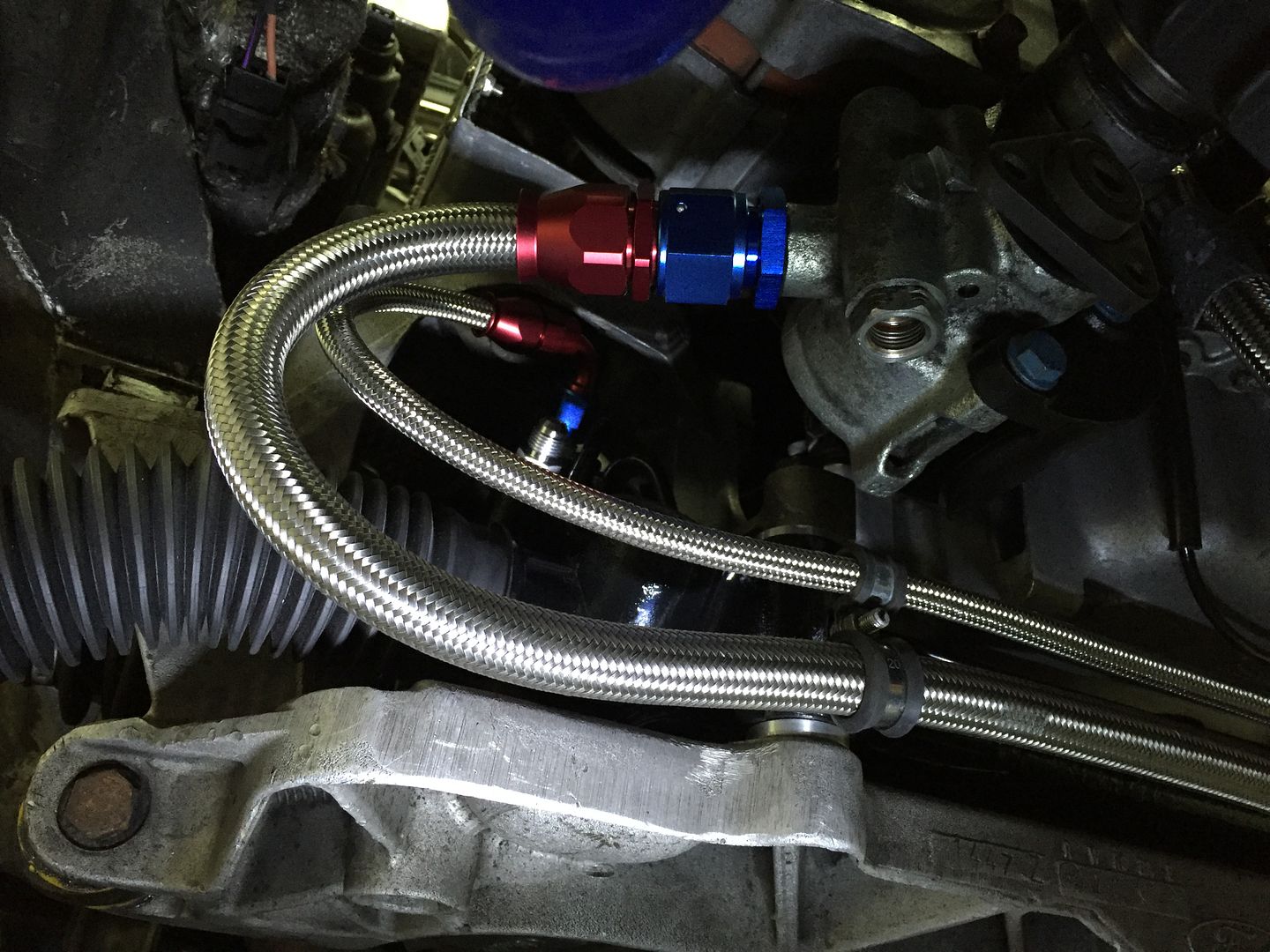
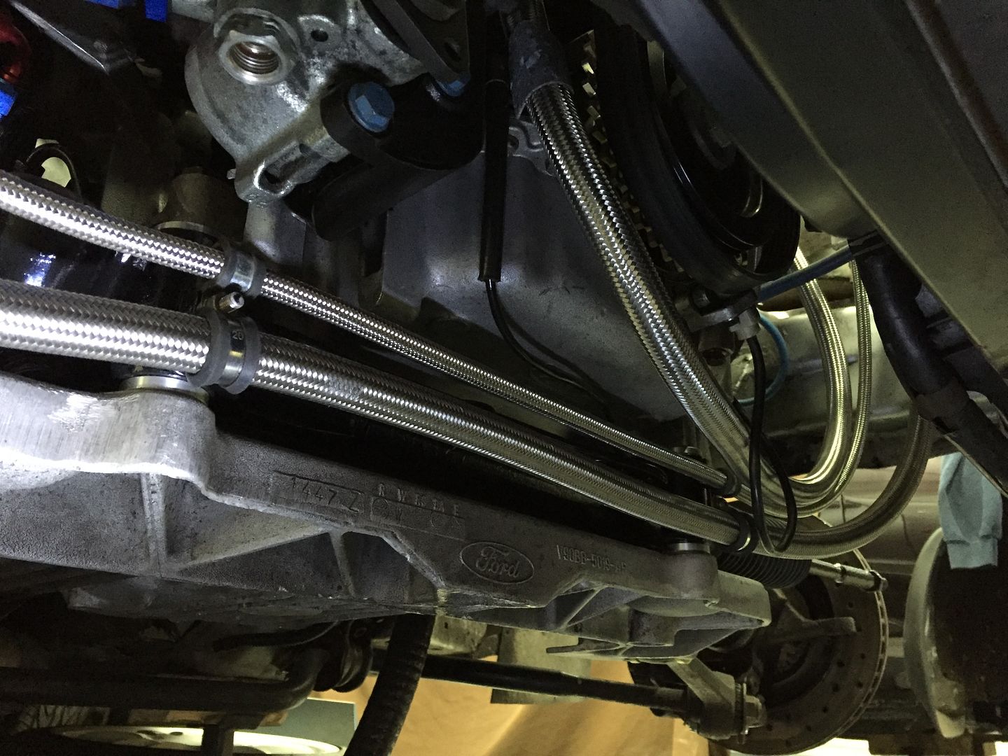
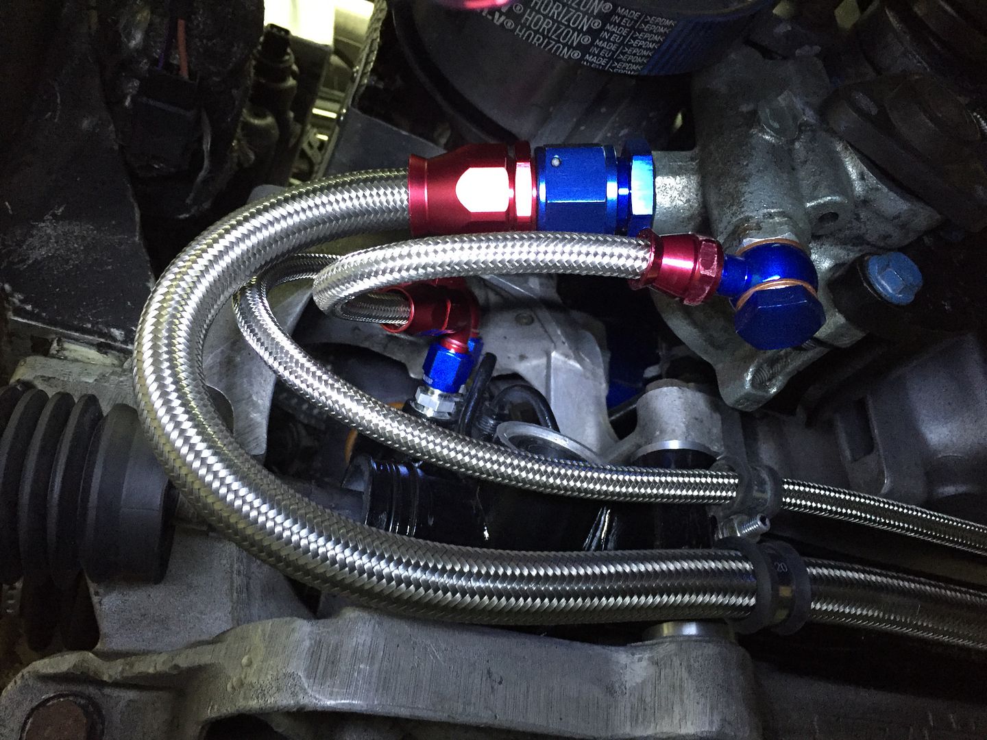
I really need to get this car out for some proper drives but at the moment the steering rack is causing me grief and it's looking like it will need a new rack and tie rod extensions to get back what I have at the moment. That and I'm also looking to AN the whole fluid system on the steering

So once again those repairs are costing a fair lump so my plans for front splitters and spoilers is put on hold!
 
Awesome thread! Loved reading this from start to finish and you really have done wonders to the car, it was also nice to be able to have the yella fella standing next to such an icon at ford fair! The S1600 kit truly is amazing in person and something I hope to achieve to mine at some point in the future. Looking forward to more updates in the future!
 
I like your puma how it is tbh Dave, its almost like a sleeper. Wide arches look nice, but I'm not sure how much handling or grip they add, so I think its mostly just for looks. One of the downsides is where the puma shines, is where the wide arches make it a pain, like country lanes, every time a car comes past its like "eeeeeeeeeeee" :lol:
 
Thanks for that, I did always want it to be a sleeper! Juts noticed you're in Chelmsford? Thats about half an hour away from us?! Keeping my eyes open for you on the roads now! The wider the track on a car, the more planted it is and feels and I'm sure there is some handling benefit but yes, it is mainly for the looks - certainly in my case. Apologies for any thread hijacking :cool: looking forward to some more updates on this car as and when they come.
 
Davedrave said:
Awesome thread! Loved reading this from start to finish and you really have done wonders to the car, it was also nice to be able to have the yella fella standing next to such an icon at ford fair! The S1600 kit truly is amazing in person and something I hope to achieve to mine at some point in the future. Looking forward to more updates in the future!

Thanks for taking the time to read it, was nice to meet you back at Ford Fair.

russv said:
I like your puma how it is tbh Dave, its almost like a sleeper. Wide arches look nice, but I'm not sure how much handling or grip they add, so I think its mostly just for looks. One of the downsides is where the puma shines, is where the wide arches make it a pain, like country lanes, every time a car comes past its like "eeeeeeeeeeee" :lol:

I would probably second this, my brother has a standard exterior to his and I think for the sleeper look you can't beat it. The arches require a lot of work to fit properly and mine to be fair still need tidying up! And yes you are very aware as to how wide he thing is when driving it!


Davedrave said:
Thanks for that, I did always want it to be a sleeper! Juts noticed you're in Chelmsford? Thats about half an hour away from us?! Keeping my eyes open for you on the roads now! The wider the track on a car, the more planted it is and feels and I'm sure there is some handling benefit but yes, it is mainly for the looks - certainly in my case. Apologies for any thread hijacking :cool: looking forward to some more updates on this car as and when they come.

No problem at all. Update to follow shortly!
 
Time for an update on progress over the last few weeks / month or so.

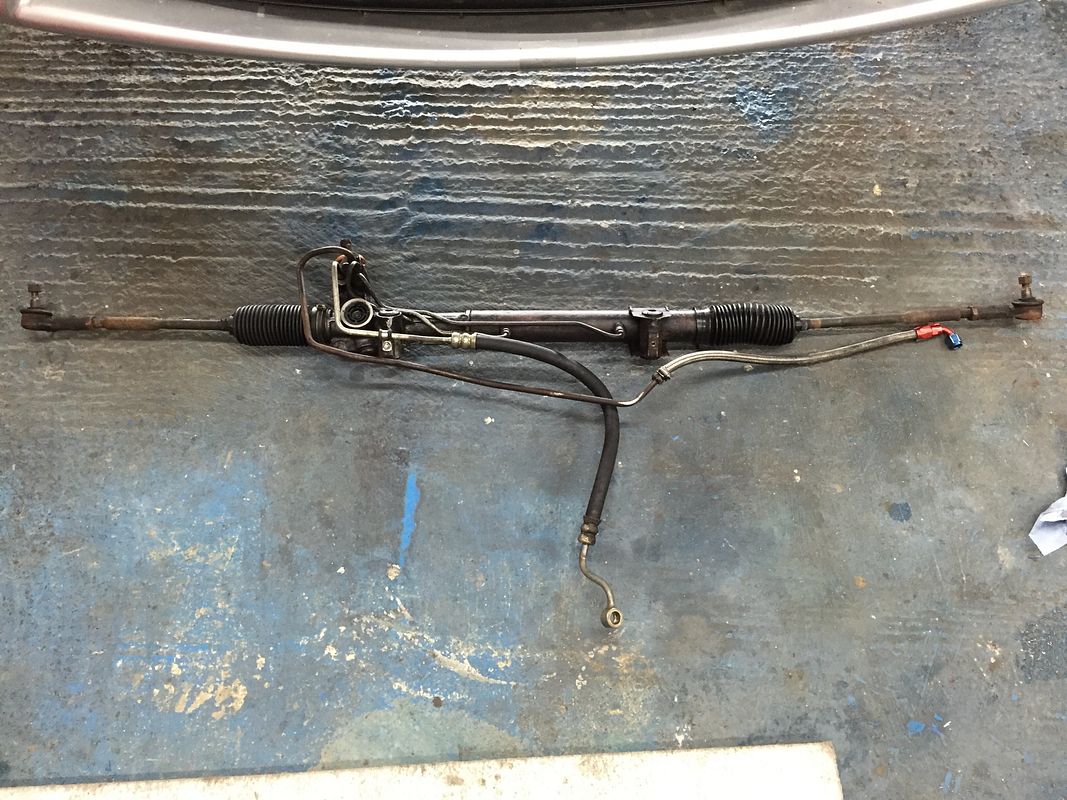
Last time out the steering rack decided it was its turn to get on the to do list and started leaking.. So out it came for new seals and while I was at it, decided it was also time to address the poor but still working steering hoses.

Rack out


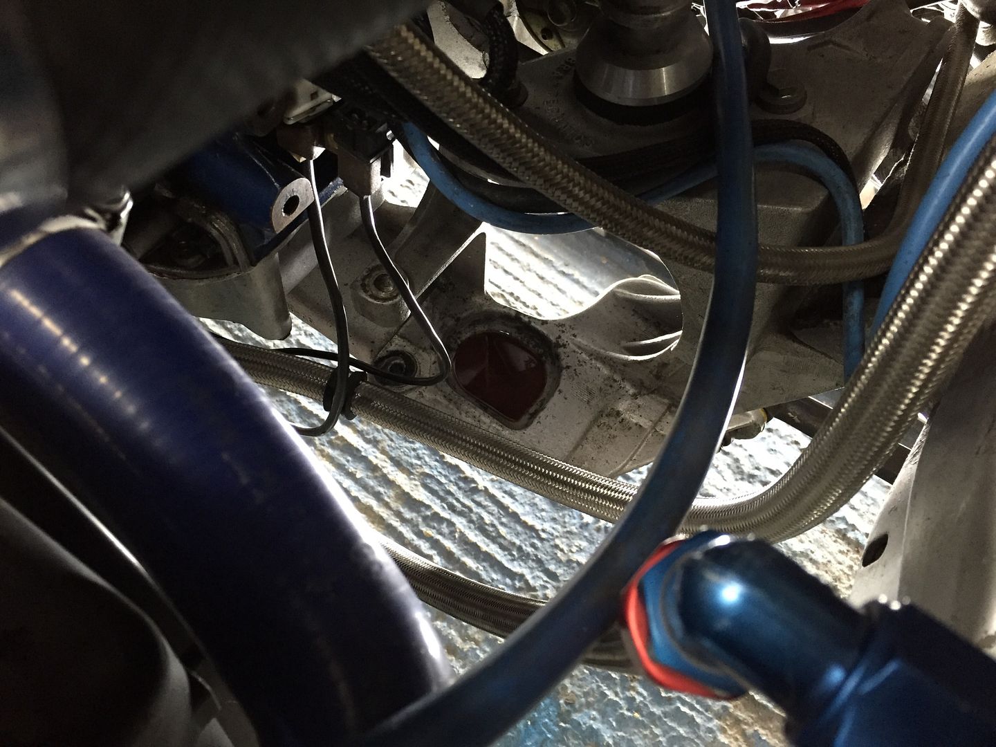
The puddle it left behind on the passenger side of the crossmember


Bit of a mess under the gaitor


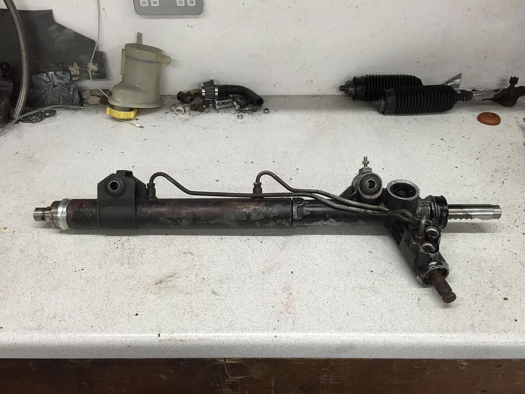
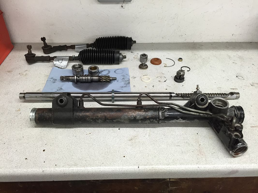
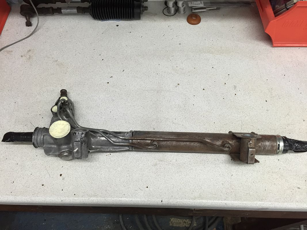
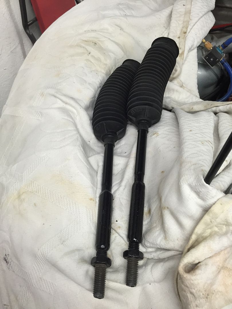
So onto the bench tie rods and gaitors taken off and time to get the rack stripped down


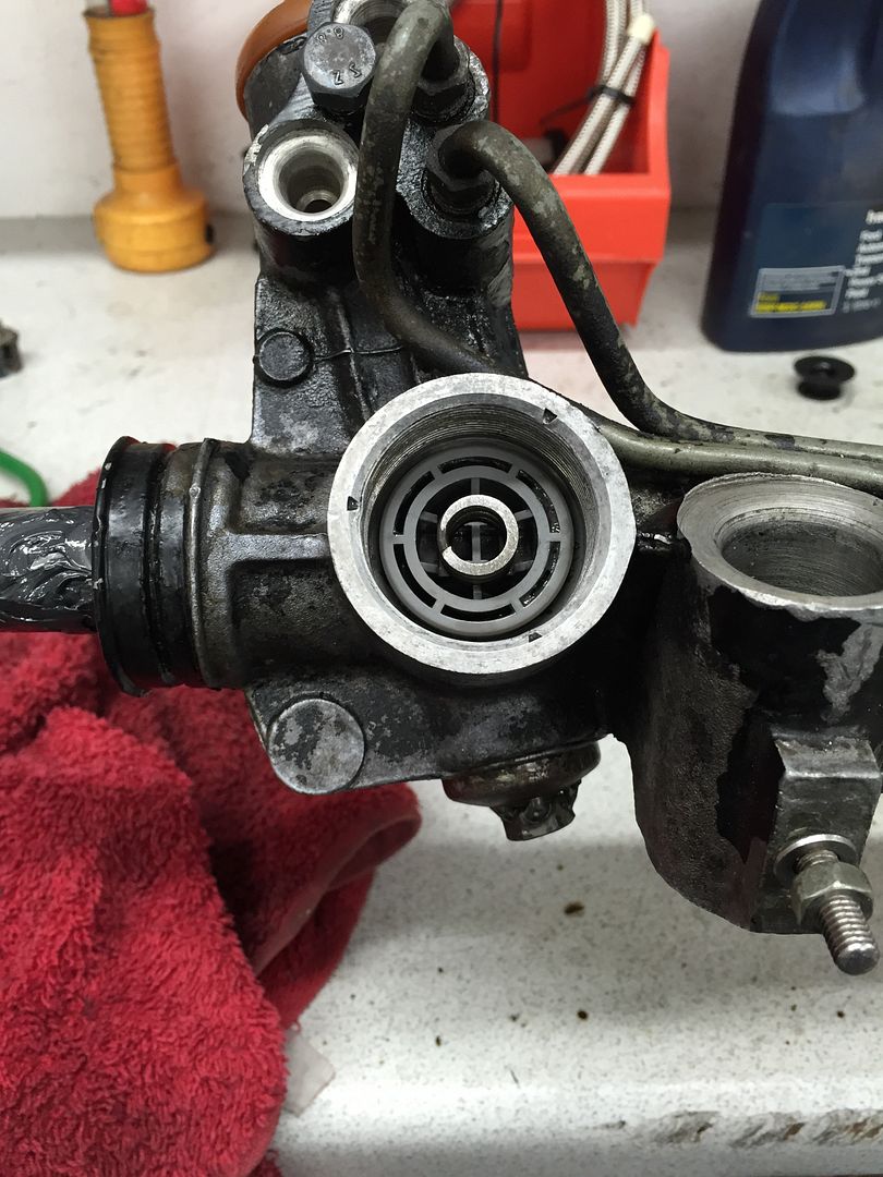
First issue was to make a tool of some kind to get the yoke cover off, so a bit of sheet metal quickly cut up, shaped and a nut did the trick just fine


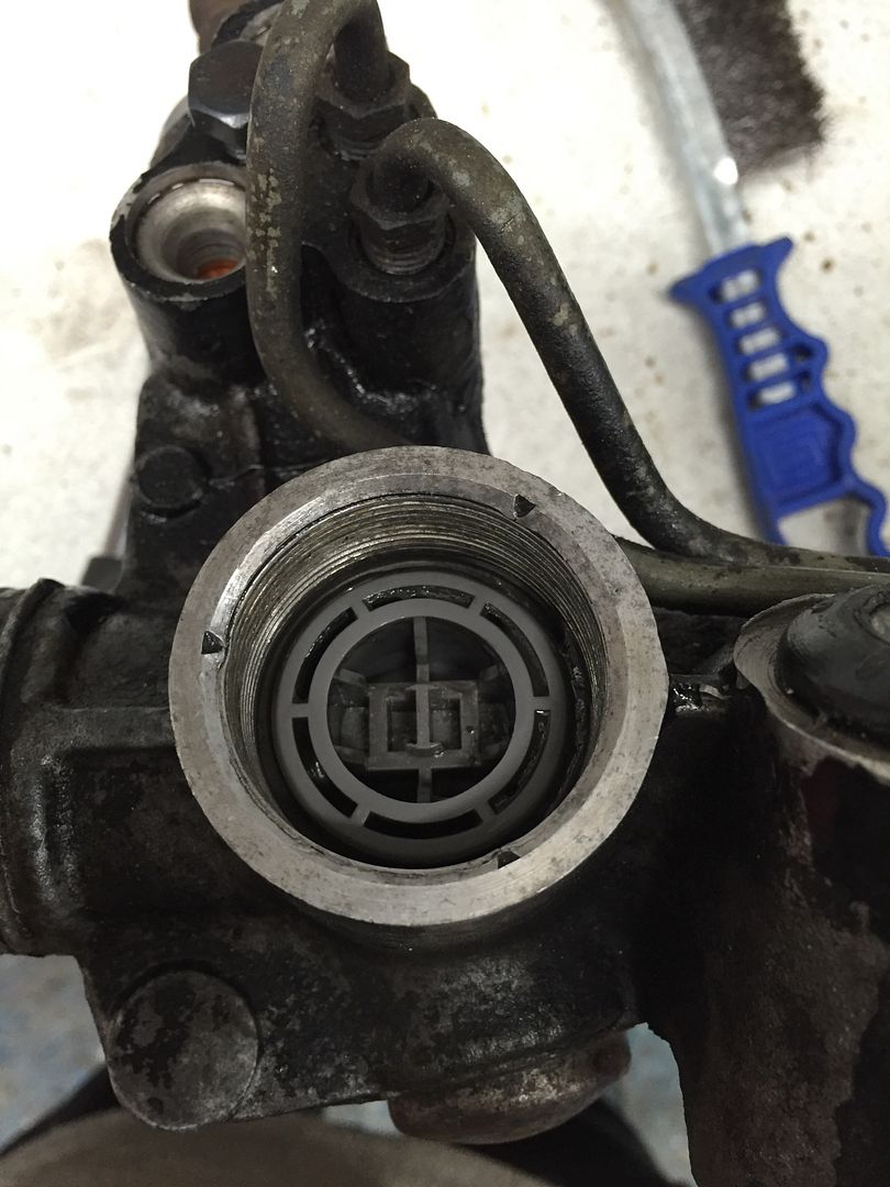
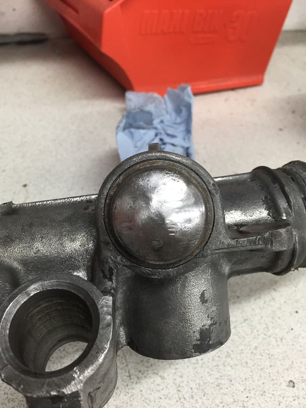
Next up was to remove the pinion nut cover.. Needed to do so without damaging the rack or cover so a quick tack weld of a nut on it I turned the cover off with ease


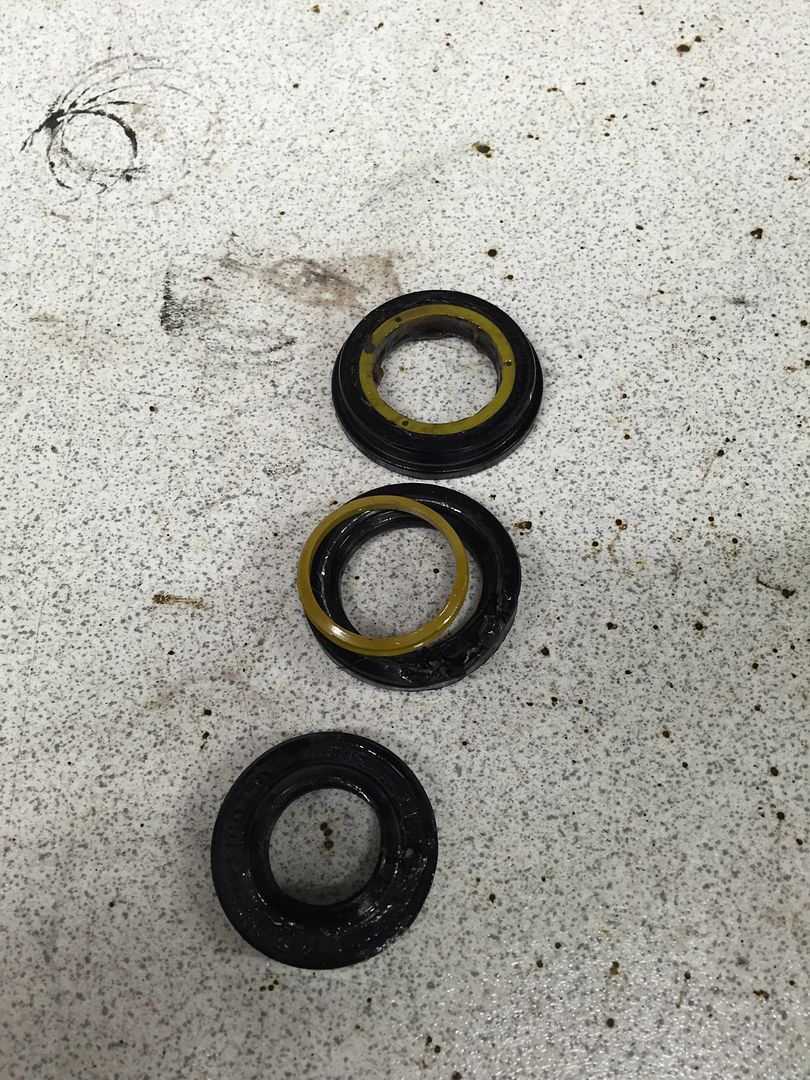
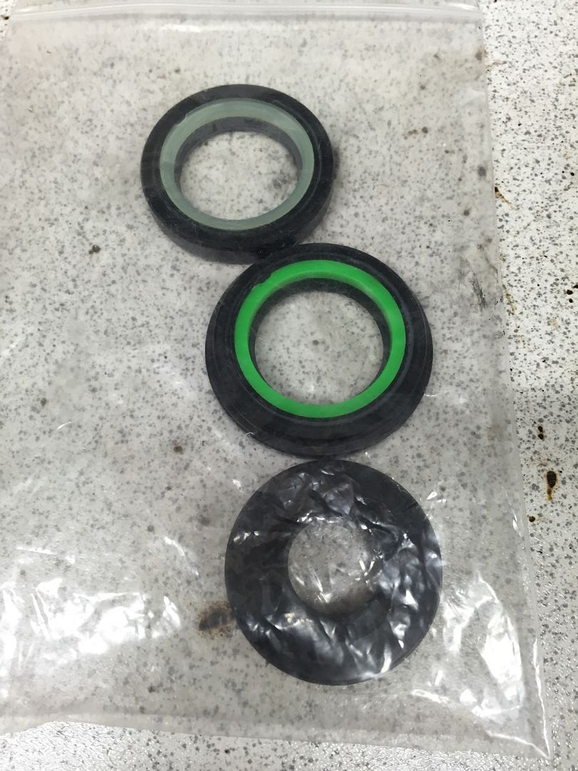
With that and a little help from the workshop manual the rack was stripped down enough for me to get the old seals out and ready for the new to be fitted


Also decided to opt for solid rack bushes and so this seemed a good time to press the old rubber mounts out


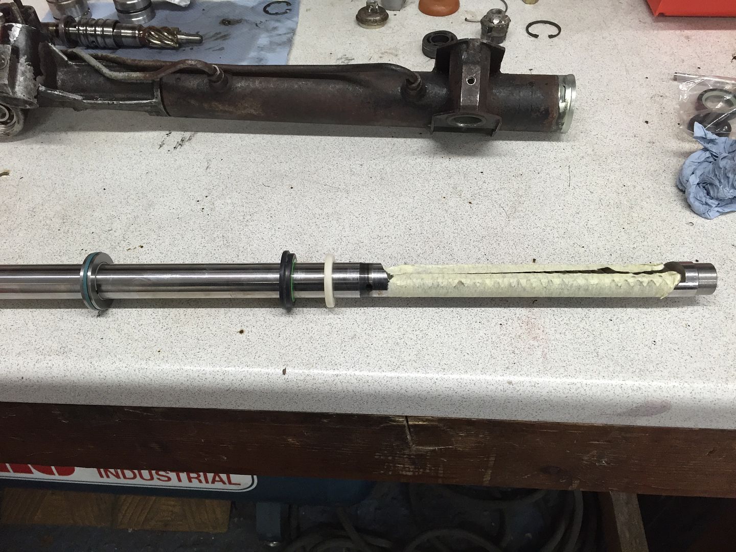
New seals being fitted - masking tape put over the rack teeth to protect the seal as I slide it on


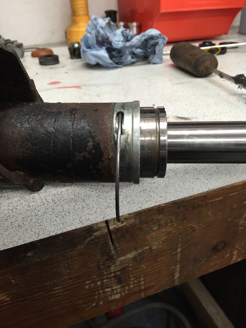
Wire re-fitted to hold seal housing in place


Pinion ready to go back in with new seal


Yoke cover ready to be refitted


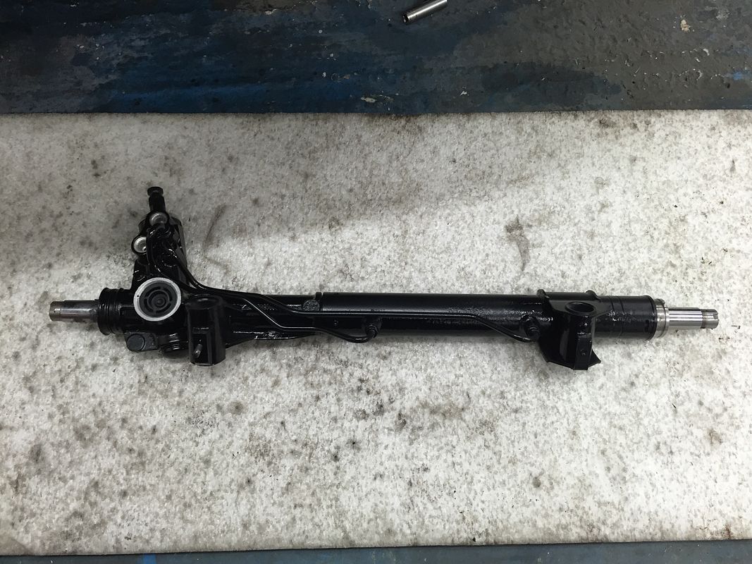
Rack built back up


Nut removed from pinion cover


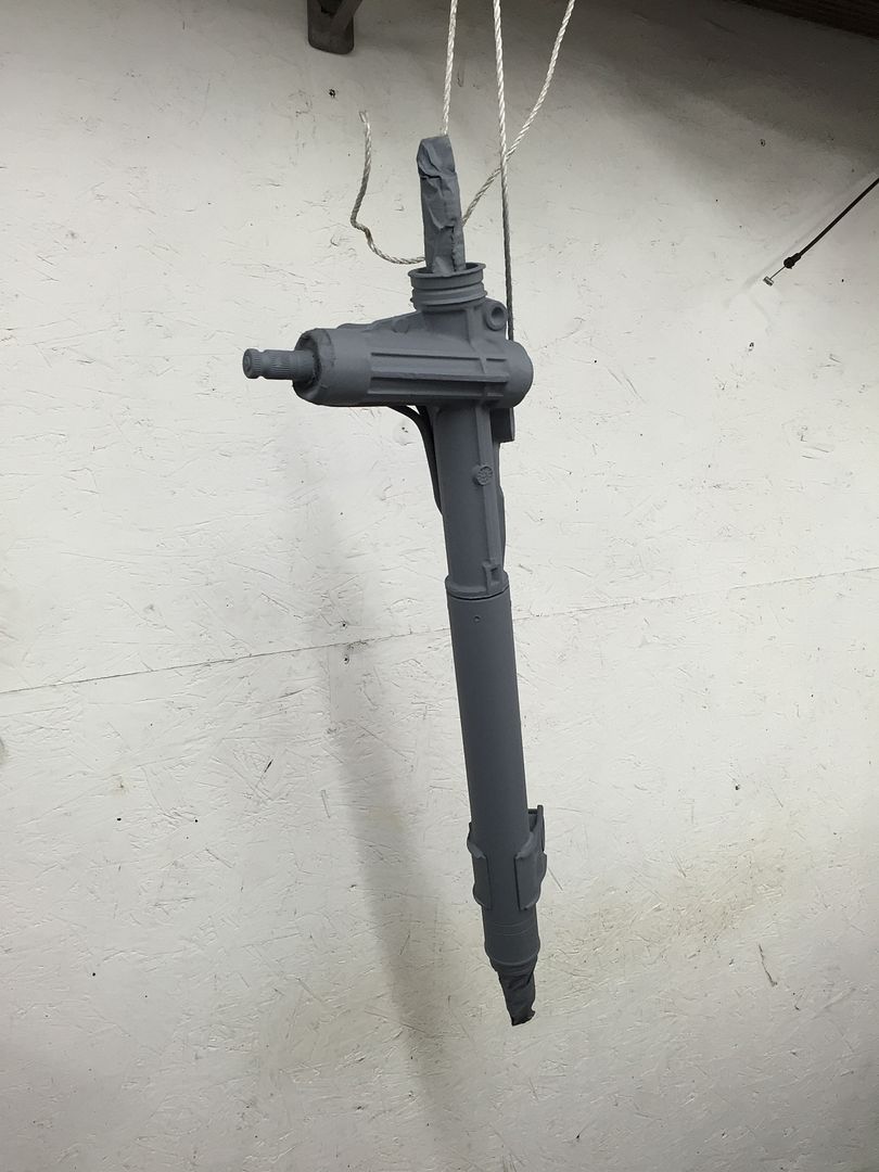
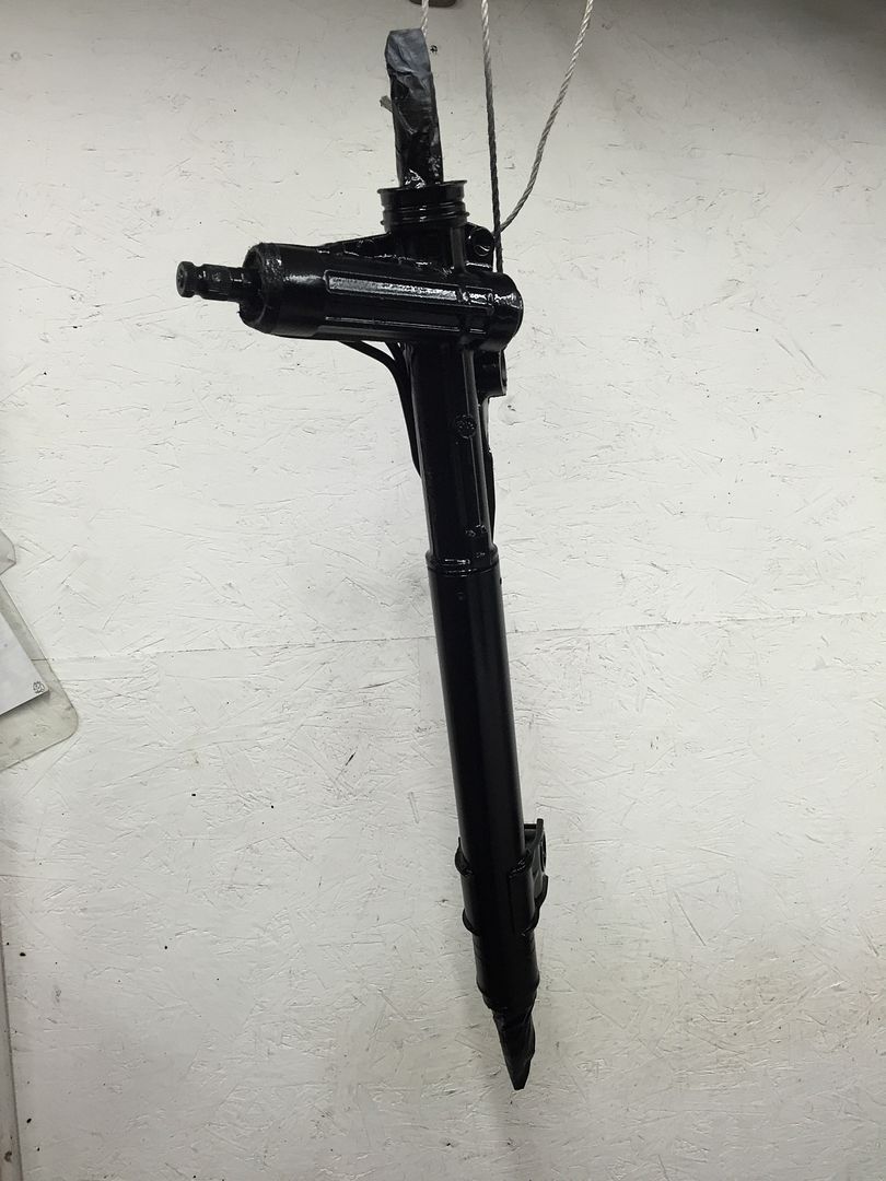
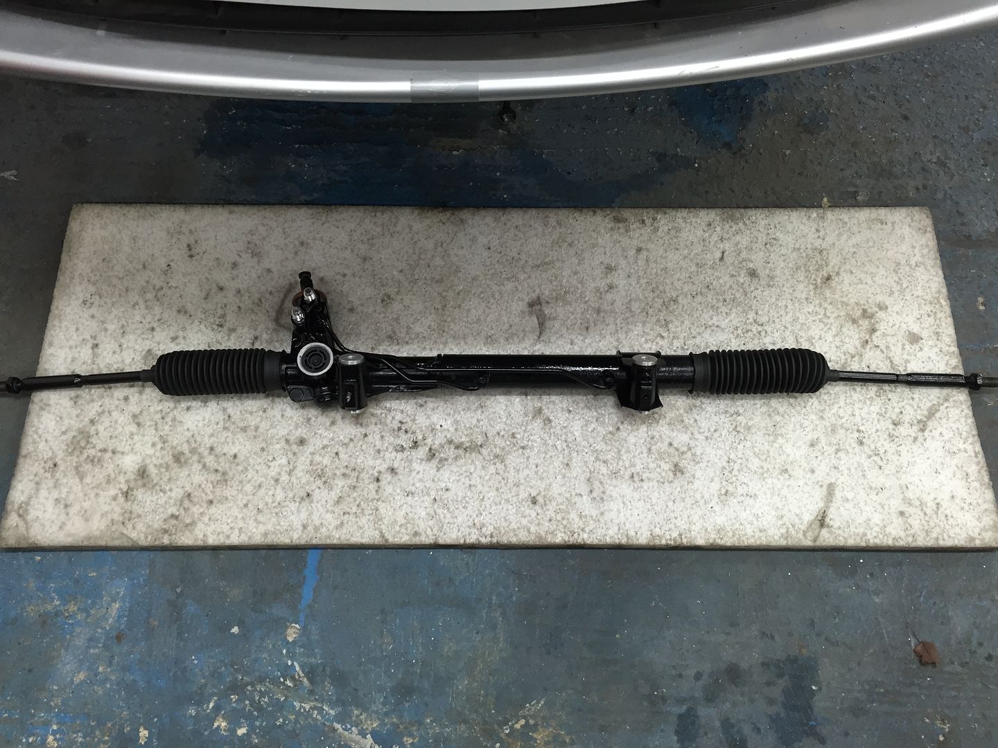
Rack cleaned and prepped ready for a bit of paint


Primer, paint and lacquer


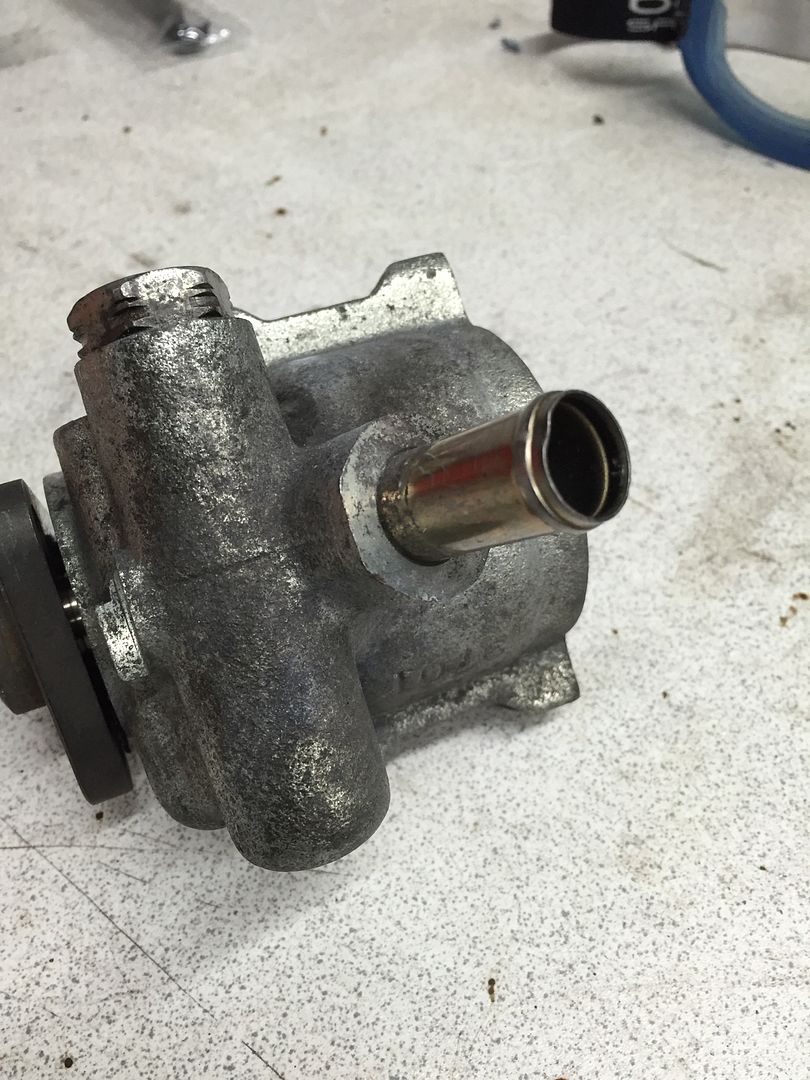
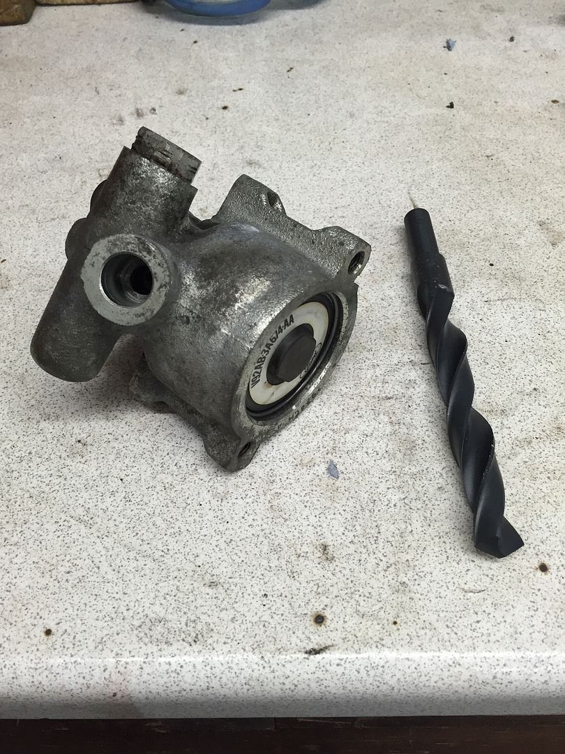
Drilled and taped the feed I let on the pump to allow an adaptor to be fitted


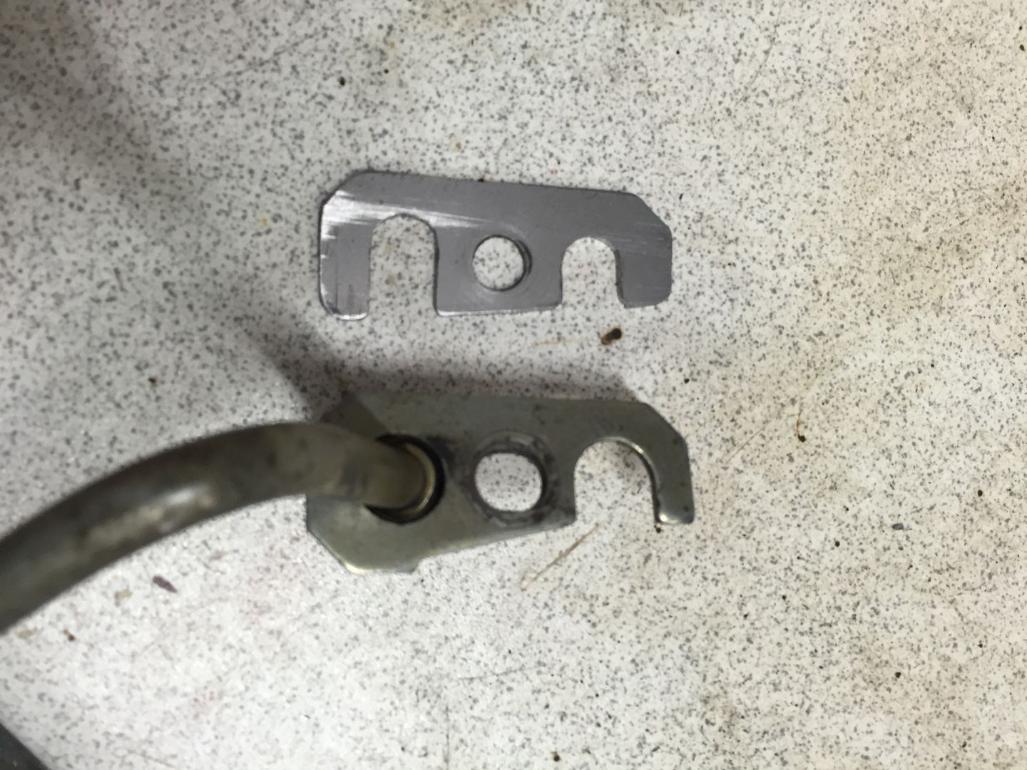
New bracket made to hold in the AN rack adaptors


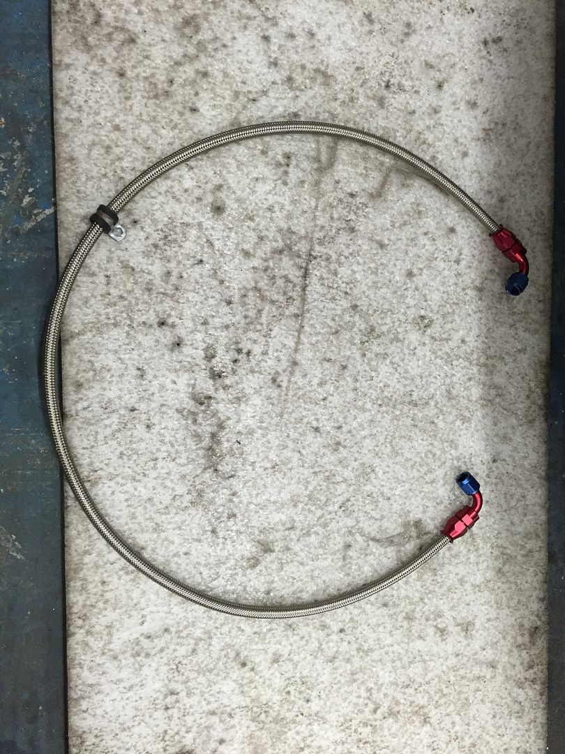
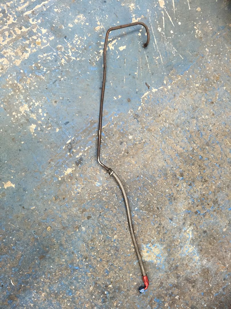
So with that done it was time to make up the new hoses and get everything fitted back together.


Old return hose now fit for the bin, old original high pressure hose sold on.


So with that all done and finally back together again it was off to get the car tracked again, having had the tie rods off and fitting new track rod ends thought it best to get it dialled back in again. All went well, great drive home again and back in the workshop


So happy that the car is back together again, though I'm now wondering whether to get out and use it a bit or start looking into that fuel tank issue.. Which will mean I'll do the rear beam at the same time..

Thanks for looking
 
Wild E. Coyote said:
Mate, this is just inspiring! Clap-clap-clap!
And a bow from me for the effort and the skill!

Thanks very much! :grin:


d170sam said:
Awesome, this is what I'm going to be doing with my rack, glad I now have a guide! Top work dude!

If I can help in any way let me know. It's quite simple when you know how it all goes together. Just make sure you centre the rack before you take anything apart and mark it so you out the pinion back in the same place. Not that I think it will matter too much.

Thanks for the comments
 
I've got nothing to add other than this is an utterly absorbing project and it's great watching the car being finished properly. A total credit to you! :thumbs:
 
Thanks very much for the comment guys, not much has happened on the car since. Haven't actually driven it either. Thinking of perhaps starting the fuel tank but we shall see.

Thanks for looking
 
So it's been a little while since the last update so thought I'd show what I've managed to get done to date on the car

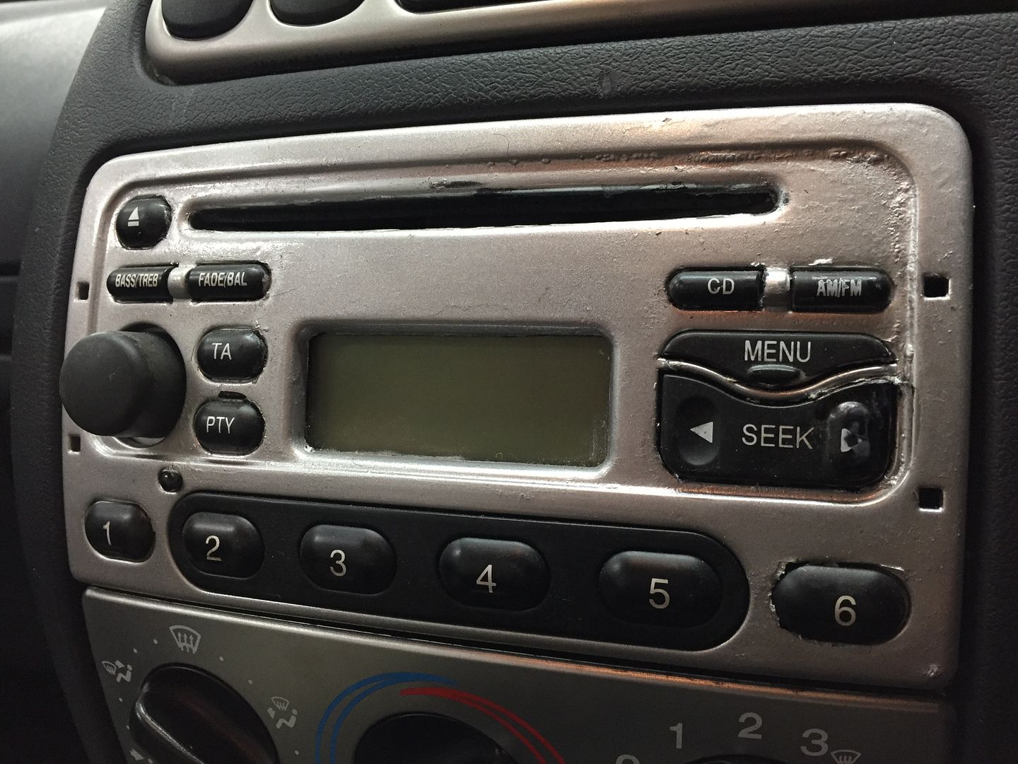
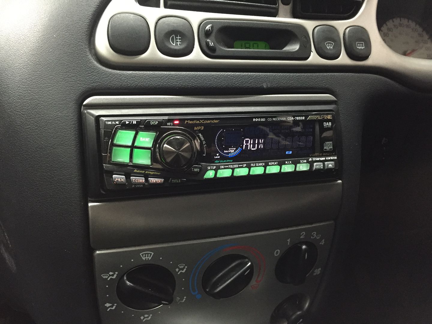
Small improvement inside.. Old 'nail varnish effect' radio out and in with a more useable headunit albeit a little old skool!


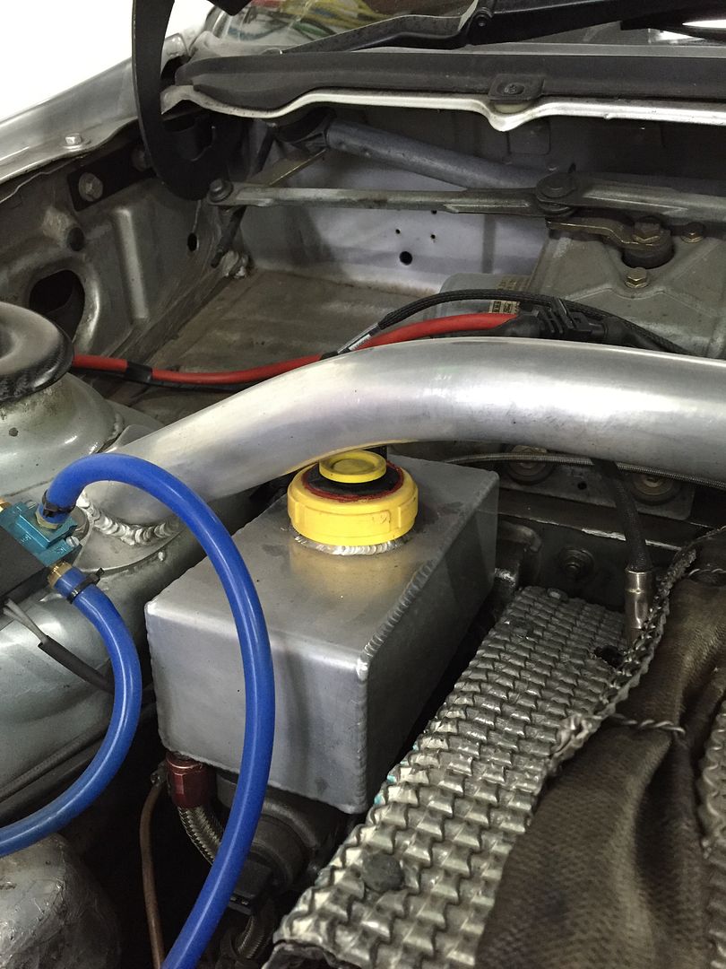
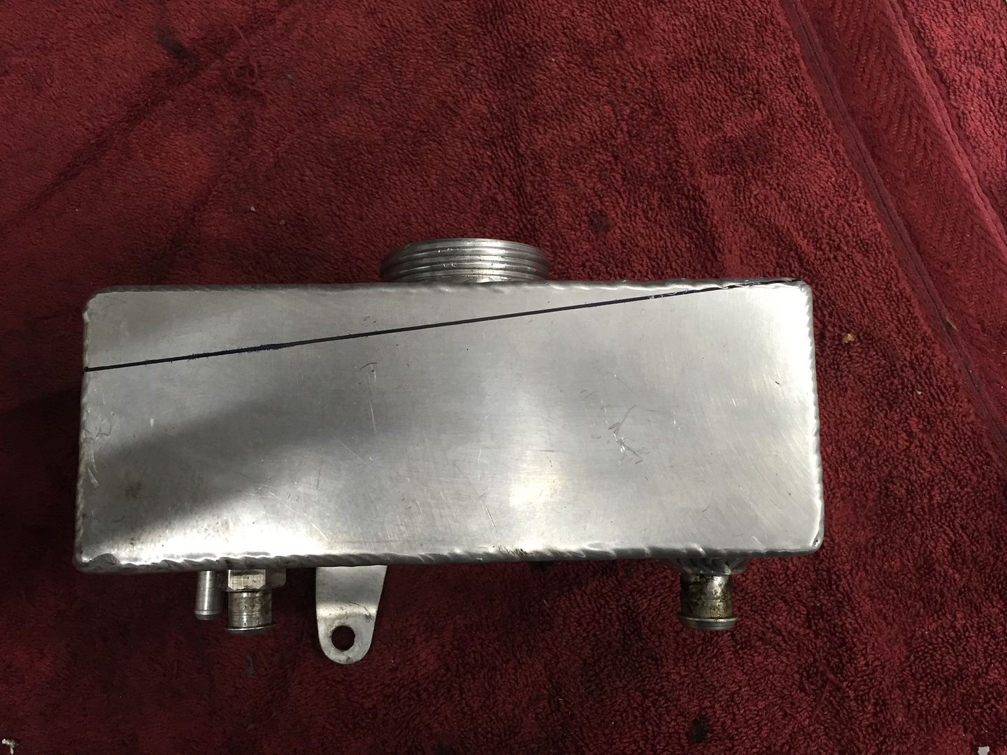
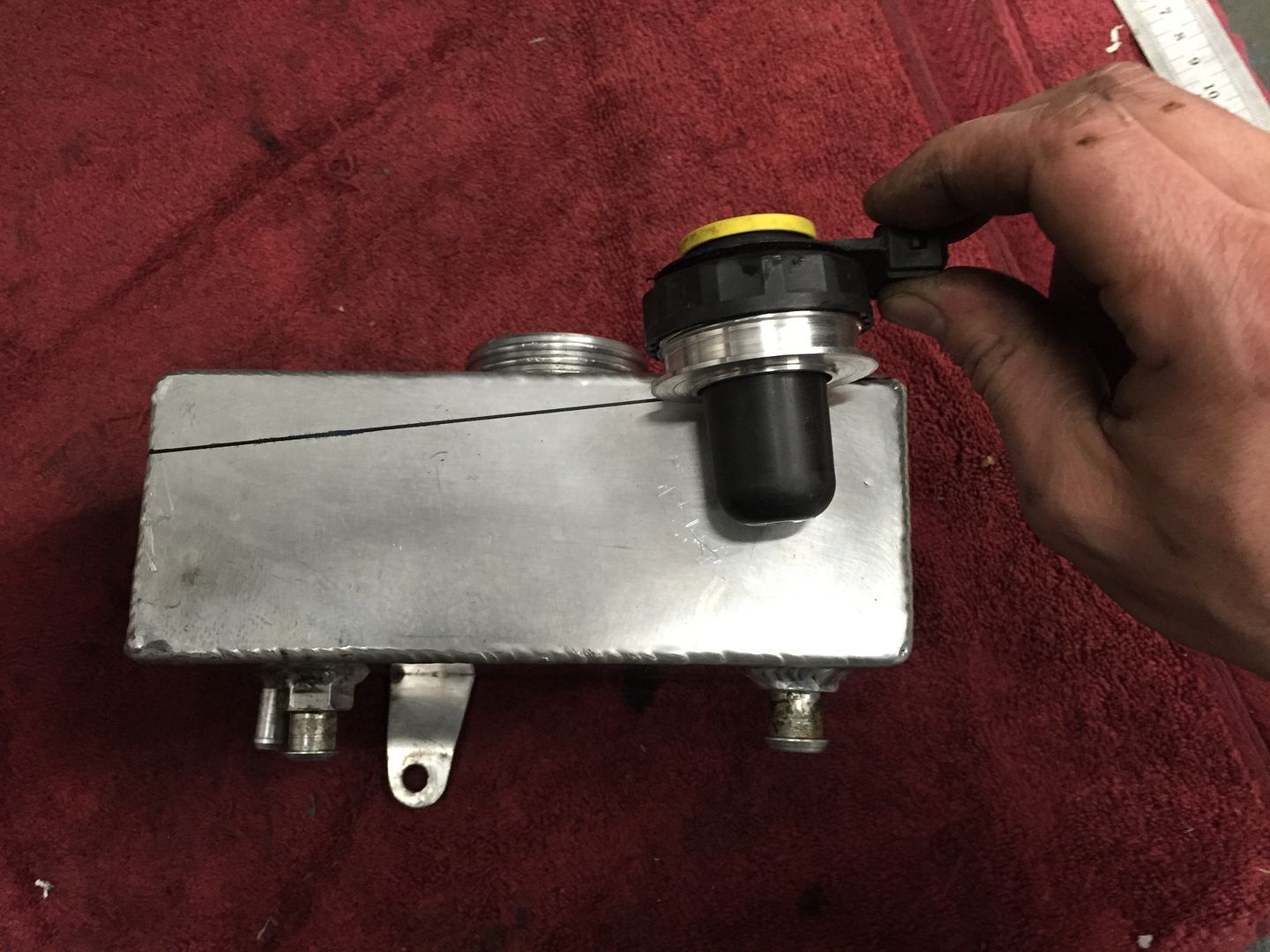
Then onto another small problem that's being annoying me for a while. The brake reservoir pot had in my opinion been made wrong in the beginning. It didn't have a flat top to it and actually angled back down to the bulkhead, it was fitted with a screw cap normally associated with a power steering bottle. This meant that the brake fluid level sensor had then been bodged into the top.


So with a little thought I came up with a better solution.

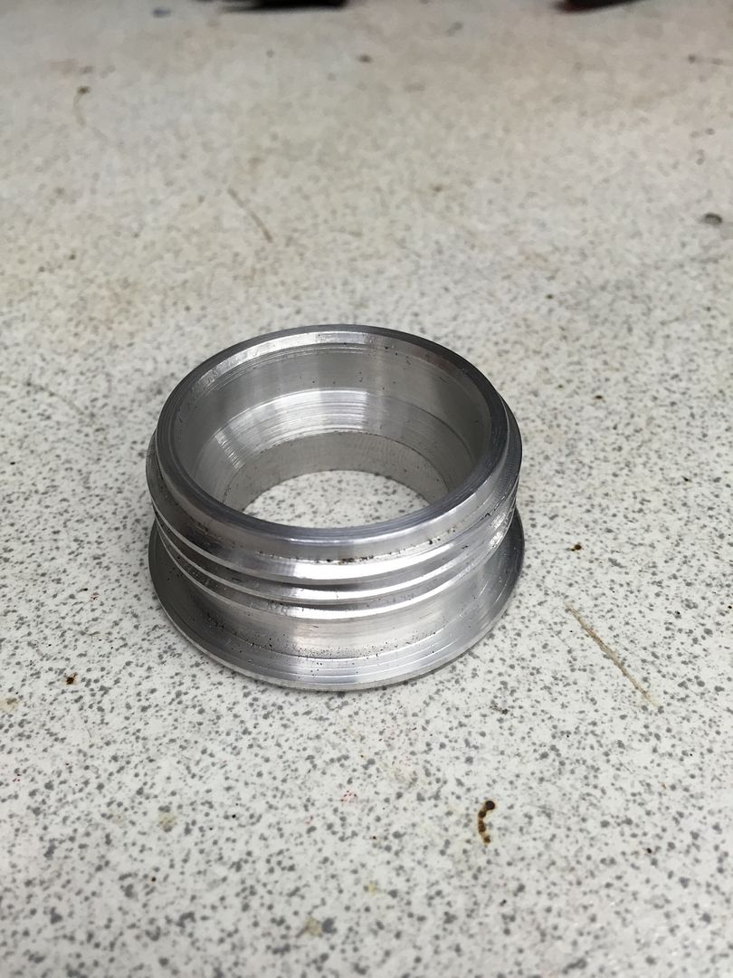
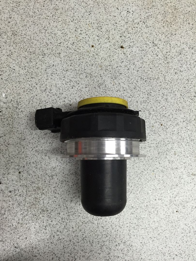
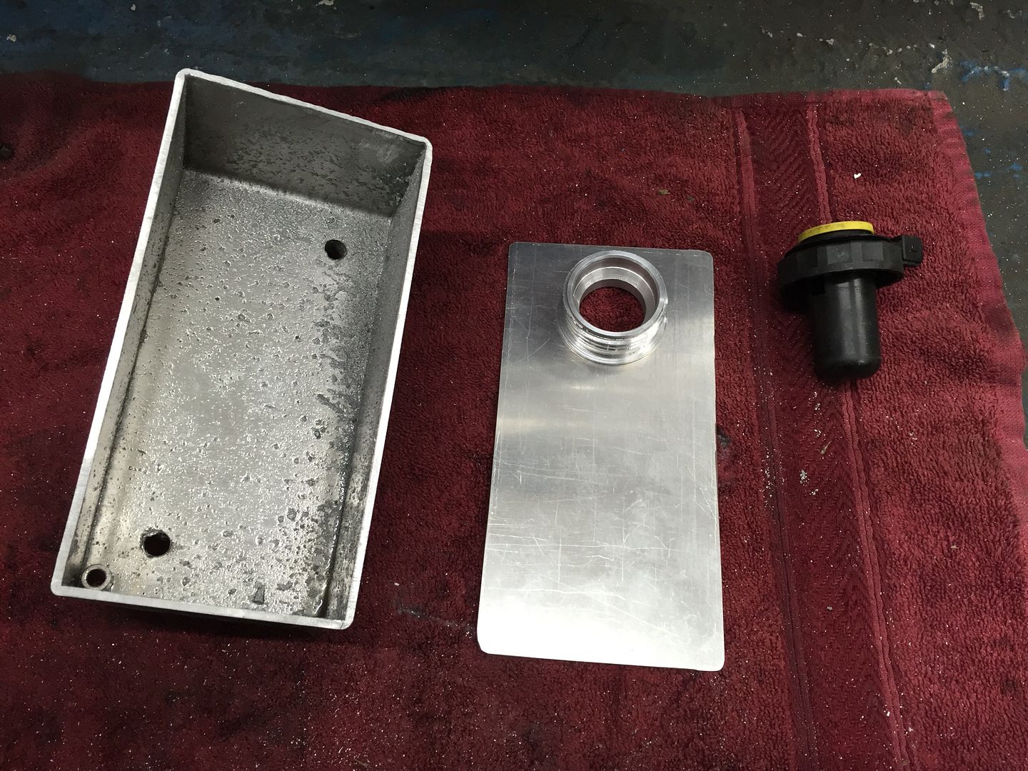
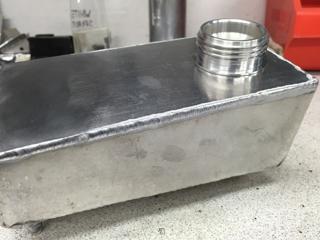
I have a friend who is quite handy with a lathe and asked if it was possible to make the correct screw thread for the factory brake reservoir cap... This is what he came out with


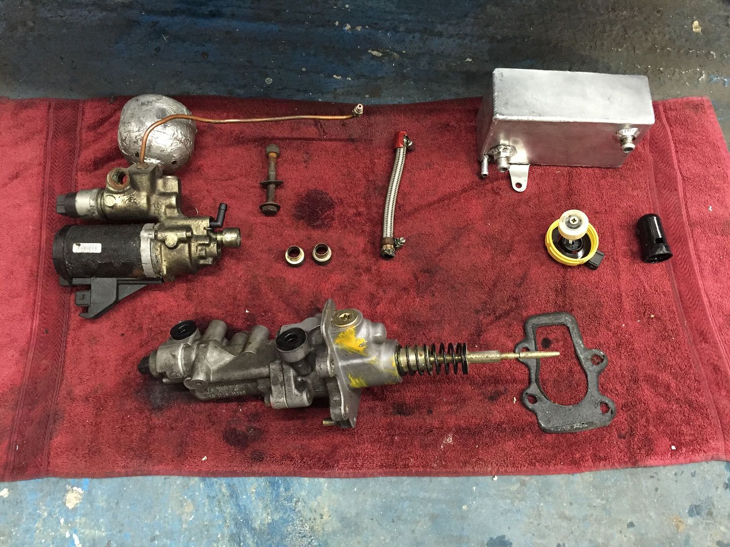
So with that made I started to remove the tank off the car, having done so I could see that over the years of leaking fluid it had attacked the paint and although not a massive issue wanted to get a better protection on before the tank went back on. I also noticed that the box made for the master cylinder had meant it came very close to the throttle cable hole. So close the cable didn't actually sit home. So made the decision to take the lot out and get it all sorted in one hit.


Also decided to take the pump out to give that a clean and check over


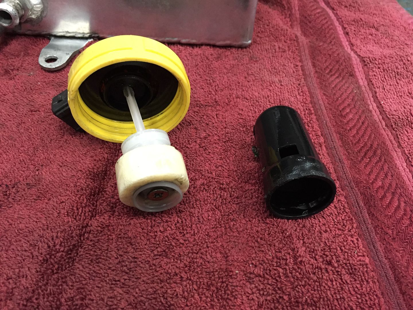
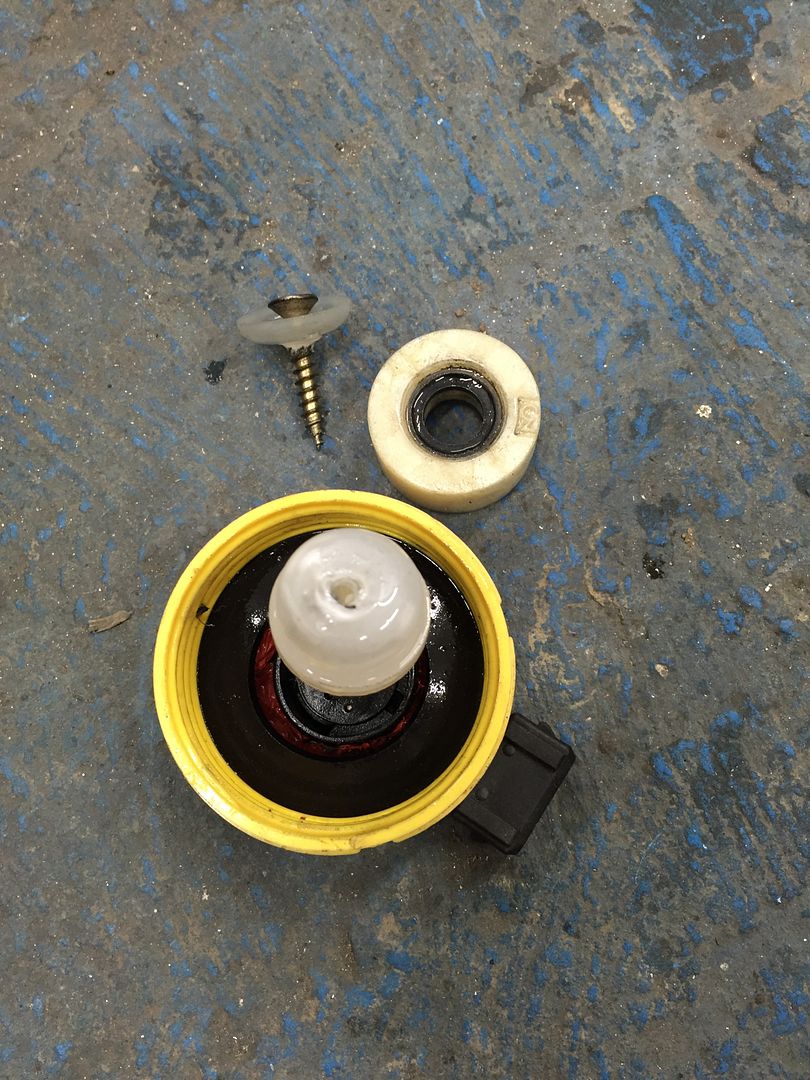
This is the interesting brake fluid level sensor float that's been adapted I assume to make it work of sorts with the sloping top to the tank


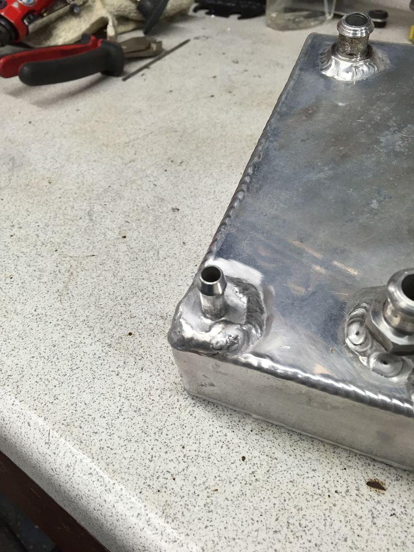
So on to adapting the tank


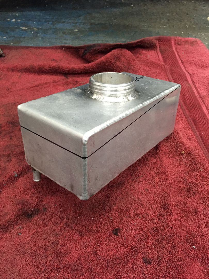
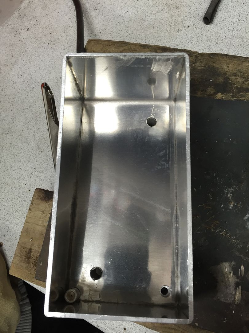
Old top cut of and levelling tank at the same time


New lid made


Whilst the tank was off I decided to add a take of for a hydraulic clutch conversion at a later date


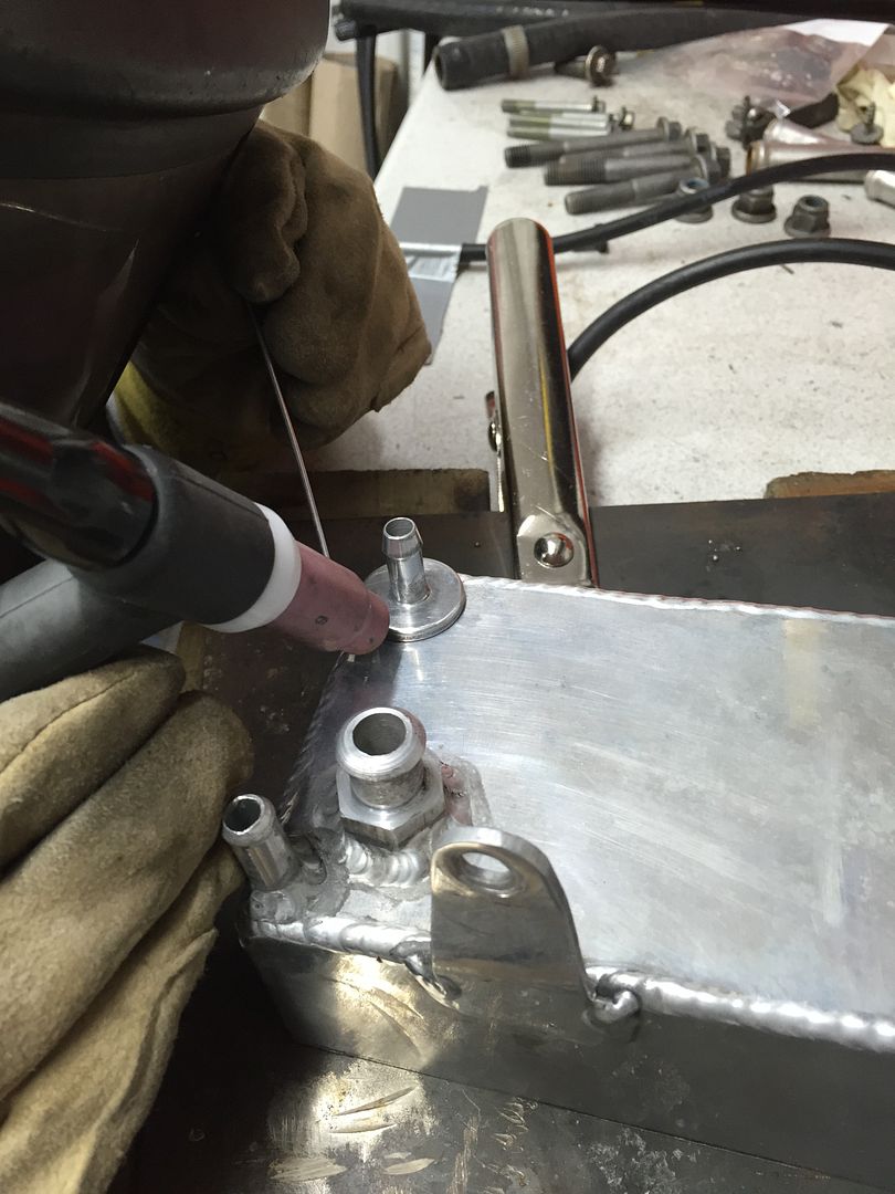
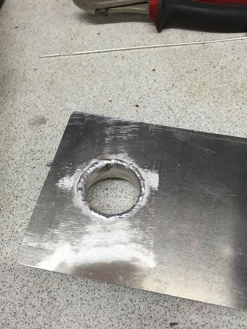
Then it was time to get it all welded back together. A while ago we bought a TIG welder as both my brother and I always wanted to learn how to weld aluminium to allow us to do more work on the cars by ourselves. So we are completely self taught and when I say we I mean my brother Ben as I have yet to spend enough time practising the art! So please be kind with our welds as we are still learning, any tips would be greatly appreciated!


That's it for now, will get the next bit of progress up shortly.

Thanks for looking
 
Great work as usual, I've yet to try it but aluminium is supposed to be really hard to weld (especially if it's not new) so well done again. I'd like to try a bit of TIGGING myself but wouldn't have a clue where to start even with buying the tackle.
Barry
 
Hi Barry,

Everything is exaggerated when welding aluminium and you don't get so much time with it. I taught myself from YouTube videos and practice on scrap pieces first. Got to be persistent and patient to learn it. You could do it though! Getting the welder and understanding it took a while for us.

That last take off pipe was a pig to weld. It was more of an alloy than aluminium and didn't want to flow into the aluminium sheet without 'diluting' it with some filler rod.

Rest of it was ok. Dan has done loads more so I'm sure he'll update again soon.
 
Yeah I'd forgotten about the different alloys as well, I suppose you'll have to have a good selection of welding rods. I tried a bit of alloy welding on my mates MIG which was really hard as the wire tended to blast through or melt in the nozzle and then unravel inside the machine. I suppose the element of control with the TIG is so much better.
Barry
 
Yes, you need a foot pedal for amperage control and ending aluminium without one is very difficult - there are settings on the machine to get around it mind, but nothing as good as a pedal.

As for rods, for aluminium a good 'all purpose' rod is the 4043, allegedly good for most applications. Again, allegedly the 2% lanthanated tungsten is a good 'all purpose' tungsten. Then it gets down gas coverage etc.

If you want to learn some more I found Jody from weldingtipsandtricks.com very useful. He's done so many YouTube videos on all types of welding and I find him very practical. All American of course as you don't find many Brits wanting to do YouTube videos to help people :lol:
 
Barry, the aluminum oxidises VERY quickly in air and that forms Al2O3 (aluminum oxide) which is rather hard to penetrate through (and that is why aluminum is not rusting as it is being protected by that layer). For that to go through you need switching polarity and thus the TIG welder needs to be AC to be able to weld aluminum. If you use DC you can't get through that al oxide initially, then you up the current and when it finally gets through that strong layer it just blasts through aluminum... That is why MIG welders struggle with aluminum, even when using the aluminum wire.
The electronics need to be very quick in reacting: when the arc is formed it has to decrease the current quickly or you are going to melt everything.... (that is the theory behind as I remember it from my studies, stand to be corrected though)
 

Latest posts

Back
Top